DC Brushed Motor Design
YOOO, doesn't this motor kinda suck. This was the first motor I designed, a DC brushed motor. This video shows the biggest flaw with brushed motors, the power connections are kind of scuffed. In order to keep the motor spinning, you have to switch the direction of current every spin, and you do that by having the connection switch what side of the communtor it is touching. However, that means that you can't have a secure connection to your communtor, meaning if it is well designed (like my connections) you can get a lot of arcs, even burning parts of the copper commutor which it was in fact what ended up happening in the video. There were other flaws with my design such as the magents being incredibly weak, but the goal was just to see if I could, which I in fact could.
LIVE, LAUGH, LOVE BLDC Motors (Brushless DC Motors for the uninitiated). These types of motors are much more efficent
typically, and are less prone to breaking down, however more complex to build increase manufactuing costs.
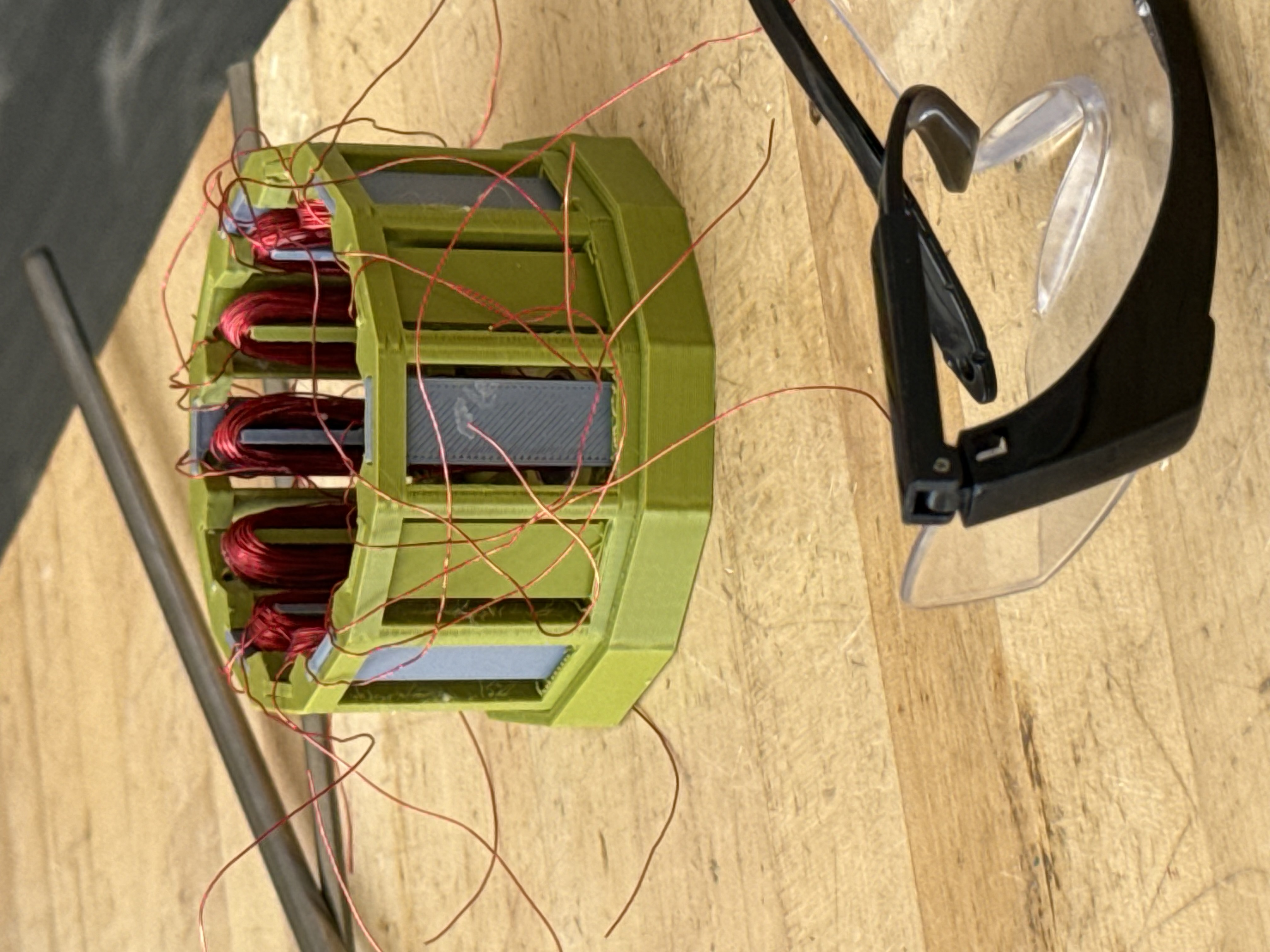
This motor is designed with a 12 slot 14 pole configuration which basically means there are 14 different magents with alternating poles
in the inside and 12 different coils on the outside. A very quick break down of how a BLDC motor works is you power one phase at a time, the magnets
move to the power coils (or away depending on polarity), then as it gets there, switch which coils you power and keep going like that. To see more info on
how the switching process works see my Electronic Speed Controller page, which to give additonal context is needed to power a BLDC Motor.
Cleaner Motor Setup
I designed a cleaner setup to hold all of my motor components. With this setup I power the motor with a 9V alkaline battery, which means it is quite off from running at full power, but was the cheapest way to power it as I already had a bunch of 9V batteries, so I went for it. I am most certinaly pulling more amps than the battery was designed for, but current ratings are fake anyways so pfttt.
Coil Winder
The full circle, USE 3D PRINTED MOTOR TO MAKE MORE 3D PRINTED MOTORS. Okay, for some context we should go back the pole slot ratio.
The motor I designed is a 12 slot 14 pole configuration, which affects its torque to RPM ratio. That configurtion is the most common way
to setup a drone, and the end goal of this project is too in fact make a drone. However, the motor I designed is much bigger than the drone
I hope to make, so I had to make smaller coils. The issue with that is, its hard to hand wind small coils like that and still make
them efficent. So, my decision was to make an electronic coil winder to do it for me.
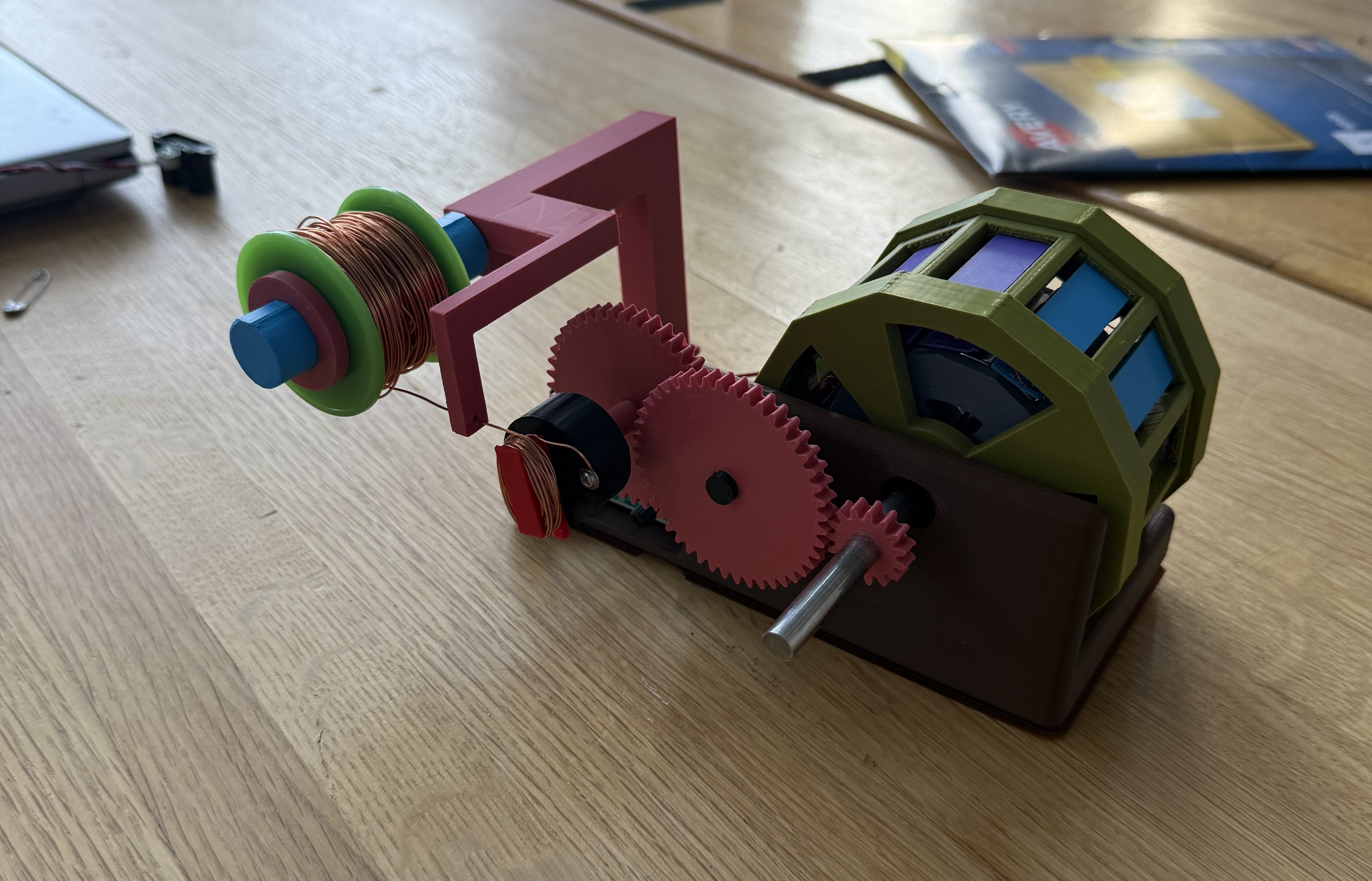
The coil winder has a bunch of gears to increase torque to ensure that it is able to pull the windings tight. The wire is then held back
with a spring to increase tension (not pictured though). The brains of the configuration is an arduino that is connected to a light sensor
that stares at the front gear that has a piece of tape on it, every time the peice of tape passes it, the winding amount goes up by one.
Once the windings hit the desired amount, a mosfet circuit shuts the motor off.