What is an Induction Heater
An induction heater uses a resonant LC tank and a pair of MOSFETs (sometimes four as well) that utilizes
Zero Voltage Switching to generate a high-frequency alternating current. Essentially the MOSFETs get turned off and
on rapidly (at resonant frequency) creating high frequency AC that goes through the inductor.
The heater coil then producses a high frequency alternating magenetic field, which
when a conductive material is place inside, the magetic field induces eddy currents within the material, and the
currents heat it up. So, if we put something with little conductance at all like our fingers, it will not heat up at all.
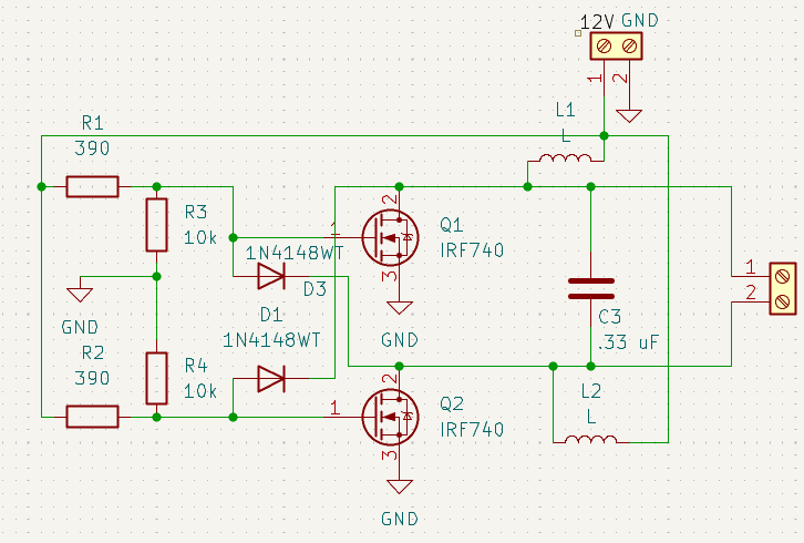
The schematic for this circuit is quite simple, but the concepts and math are quite interesting (technically in a perfect world, an induction heater
would not even work as both mosfet gates would open at the same time preventing self-oscillation, but we can infer once is more conductive than the other in the real world)
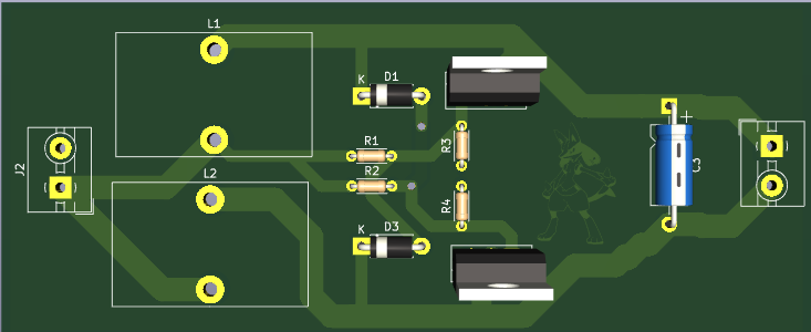
PCB Layout
The PCB consists of two toroidal coils that acts as chokes to reduce electrical noise and blocks AC current coming back into the input supply. The mosfets are used for switching the direction of current through the LC resonant tank, and of course the capacitor and heating inductor are used to form the LC tank.
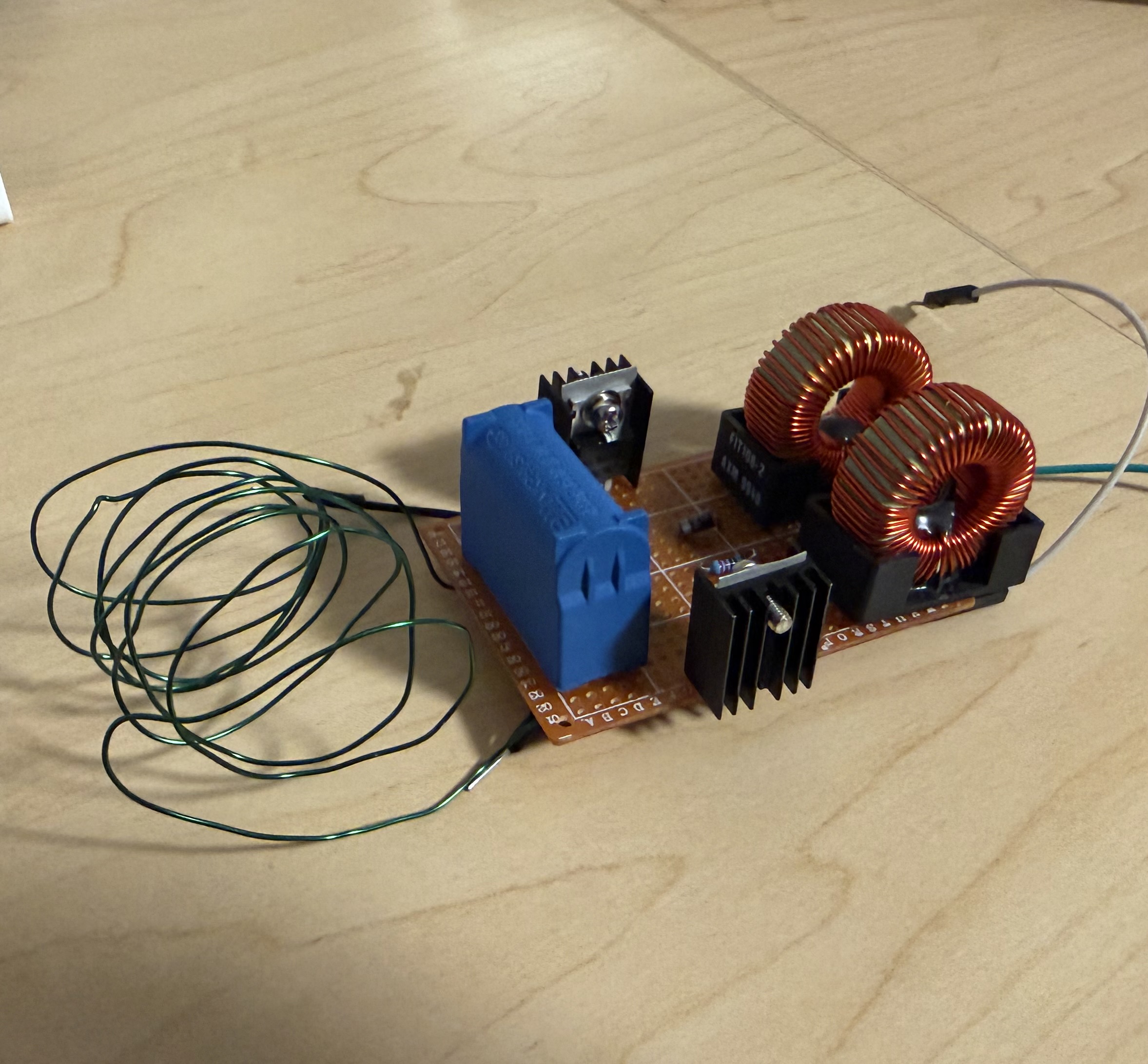
Prototype
After creating a schematic I quickly developed a protoype to test if my schematic values would actually end up working before I order the PCB. I ran 4 volts through the board and was able to draw over an amp, but as I increased the voltage, I found that I vastly underestimated the size of MOSFET heat syncs needed and one of them quickly burnt out. However, besides that the prototype showed promising results so I ordered the PCB.